How to Work Out Which Load Arrestor you Require
All models tell you all you need to know, LA300-12 for example, LA = Load Arrestor, 300 = the maximum load the arrestor can be used for and -12 is the cable length in metres that can be used. All you then need to specify is your activation speed, for this unit you have a choice of 0.3, 0.5 and 1.0 metre per second. This means for a load up to 300kgs with a cable length of 12 metres and an activation speed of 0.5 metres per second your order would be for an LA300-12 0.5m/s.
If you need a longer cable length this may be able to be achieved if the arrestor is, for instance, being fixed higher than the load. You still only need 12 metres to recoil into the housing but are 3 metres above the load constantly you would then need to order a LA300-12+3 and the activation speed. The extra cable length is limited by the increased weight of the cable as too much will stop the unit from retracting the wire rope. For lengths over 4 metres please talk to our technical department.
Load is doubled and cable length halved if the unit has a pulley, so an LA300-12 becomes an LA600-6P, all pulley units can only have activation speeds of 0.5 metres per second. This is because they use a 1.0 metre per second spring but because the wire rope travels double the distance the operating speed is 0.5 metres per second.
Load Arrestor General Information
The Sala range of Industrial Load Arrestors are safety devices used in conjunction with lifting devices, such as cranes and hoists. The arrestor provides independent protection that will arrest the fall of a load in the event of the primary system failing and, being completely independent of the primary lifting system, it reduces the risk of equipment damage and protects personnel in and around the danger zone.
A range of arrestors in each of the three series is available to protect loads from 100kgs to 3000kgs with a variety of wire rope lengths based on the three model sizes, small, medium and large. The arrestors can also be used in conjunction with other arrestors of the same size to be able to achieve a desired working load capacity. For instance three LA3000-7.5P could be used to protect a load of 9000kgs, this makes them very versatile. The use of multiple units should be discussed with our technical team as there must be sufficient distance to allow the other unit to activate.
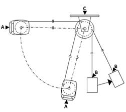
The picture shows how two load arrestors can be used together to achieve the higher working load than one unit can manage.
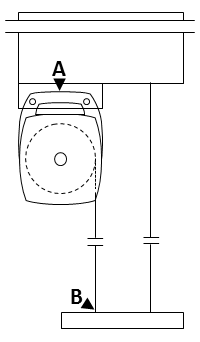
The load arrestor is installed adjacent to the primary lifting device and fixed to a suitable anchorage point. Its retractable steel rope is then secured to the load. The wire rope is attached to the arrestor via an internal spring loaded drum that keeps the rope under a constant light tension yet allows unrestricted movement of the protected load.
In the event of a failure of the primary lifting device that allows the load to fall or descend too quickly, the arrestor senses a descent speed in excess of its setting of either, 0.3, 0.5 or 1.0 metre per second and automatically engages an internal inertia activated mechanical brake that acts on the rope drum. This decelerates and stops the lowering of the suspended load within a minimum of 100mm to a maximum distance of 1300mm and absorbs the shock forces.
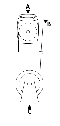
Installing a Load Arrestor in cramped conditions may be overcome by using a pulley. The arrestor must always be installed so that the wire rope operates straight from the drum to the pulley as shown in the picture, with both drum and pulley rotating in the same direction and with the path of the rope following the curve or coil of the rope. Do not allow the rope to be coiled in the opposite direction.
Using a pulley in this manner so as to ensure a straight run into the unit you can still choose all available operating speeds for the unit you require.
This now also enables the load to be at various angles because the feed to the block remains straight.
For anchorage requirements please refer to the charts below.
| Minimum Anchorage Requirements - Rope Direct to Load | ||
| LA Model | Anchorage A(kN) | Anchorage B(kN) |
| LA300-12 | 16.0 | 16.0 |
| LA400-8 | 24.0 | 24.0 |
| LA500-5 | 32.0 | 32.0 |
| LA500-20 | 32.0 | 32.0 |
| LA800-17 | 41.0 | 41.0 |
| LA1000-12 | 48.0 | 48.0 |
| LA1000-14.13 | 48.0 | 48.0 |
| LA1500-5 | 71.0 | 71.0 |
| LA1000-30 | 48.0 | 48.0 |
| LA1300-20 | 59.0 | 59.0 |
| LA1500-15 | 71.0 | 71.0 |
| LA1750-13 | 78.0 | 78.0 |
| Minimum Anchorage Requirements - Rope Via Pulley On Load | |||
| LA Model | Anchorage A(kN) | Anchorage B(kN) | Anchorage C(kN) |
| LA600-6P | 16.0 | 16.0 | 32.0 |
| LA800-4P | 24.0 | 24.0 | 48.0 |
| LA1000-2.5P | 32.0 | 32.0 | 64.0 |
| LA1000-10P | 32.0 | 32.0 | 64.0 |
| LA1600-8.5P | 41.0 | 41.0 | 82.0 |
| LA2000-6P | 48.0 | 48.0 | 96.0 |
| LA2000-7.05P | 48.0 | 48.0 | 96.0 |
| LA3000-2.5P | 71.0 | 71.0 | 142.00 |
| LA2000-15P | 48.0 | 48.0 | 96.0 |
| LA2600-10P | 59.0 | 59.0 | 118.0 |
| LA3000-7.5P | 71.0 | 71.0 | 142.0 |
| LA3500-6.5P | 78.0 | 78.0 | 156.0 |
| If upper anchorage is designed as one assembly the capacity must be the total of A + B. | |||
Whilst each range of load arrestor works in the same way their physical size and weight are very different. Each range has been designed so that there is no lag in the activation speed by only offering a limited number of pawls, so the Small has 4, the Medium 6 and the Large 8. This ensures that the unit detects and activates as soon as the over speed is detected.